
Add a device
Add a wired device to your BRNKL 5G by connecting it to the appropriate slot on the BRNKL connector, then configuring it in the BRNKL app.
Video walkthrough
Connector slots
The BRNKL 5G connector has 14 slots. Each slot is dedicated to a specific input type.
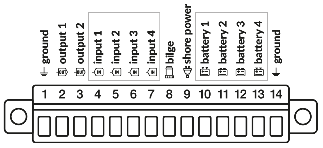
Slot | Function | Notes |
|---|---|---|
1 | Ground | Common ground reference for all inputs |
2 | Output 1 | Switched ground output — do not apply voltage |
3 | Output 2 | Switched ground output — do not apply voltage |
4 | Input 1 (digital) | Switch to ground to trigger — do not apply voltage directly |
5 | Input 2 (digital) | Switch to ground to trigger — do not apply voltage directly |
6 | Input 3 (digital) | Switch to ground to trigger — do not apply voltage directly |
7 | Input 4 (digital) | Switch to ground to trigger — do not apply voltage directly |
8 | Bilge | Connect bilge pump manual/switching lead; accepts positive voltage when pump runs |
9 | Shore power | Connect Shore Power Sensor +Vo output; sensor sold separately |
10 | Battery 1 | Connect battery positive through a 3 A fuse; accepts 0–30 V DC |
11 | Battery 2 | Connect battery positive through a 3 A fuse; accepts 0–30 V DC |
12 | Battery 3 | Connect battery positive through a 3 A fuse; accepts 0–30 V DC |
13 | Battery 4 | Connect battery positive through a 3 A fuse; accepts 0–30 V DC |
14 | Ground | Common ground reference for all inputs |
General workflow
Disarm BRNKL.
Remove the connector.
Wire the device to the appropriate connector slot. See the device-specific guide for wiring details.
Reattach the connector.
In the BRNKL app, go to Settings > Devices and scroll to find the slot you used.
Turn on Monitor and configure settings for that slot (see below).
Tap Save.
Wait 15 minutes for settings to sync, then test the device.
Input types and settings
Each slot has a fixed input type. The settings available in the BRNKL app depend on which type you are configuring.
Common settings
These settings appear on every sensor type.
Monitor — displays the sensor as a tile on the BRNKL dashboard.
Alert — sends a notification when the sensor changes state or crosses a threshold, while the system is armed.
Name — label shown on the dashboard and in alerts. Use 12 characters or fewer for best display.
Battery / analog (slots 10–13)
Used for monitoring DC voltage sources such as batteries. Reports a continuous voltage reading.
Decimal Places — number of decimal places shown for the voltage reading.
Offset Voltage (V) — constant added to the raw reading, used to calibrate the displayed value.
High Voltage Alert (V) — alerts when voltage rises above this value.
Low Voltage Alert (V) — alerts when voltage falls below this value.
Bilge (slot 8)
Used for monitoring bilge pump activity. Reports on/off state and tracks pumping frequency over time.
High Name — label shown when the bilge pump is running (default: On).
Low Name — label shown when the bilge pump is off (default: Off).
Long Period Alert — alerts when pumping events exceed the Long Period Alert Limit within the set time window. Useful for catching slow leaks.
Long Period Alert Limit — maximum number of pumping events allowed in the long period before an alert is triggered.
Short Period Alert — alerts when pumping events exceed the Short Period Alert Limit within the set time window. Useful for catching sudden flooding.
Short Period Alert Limit — maximum number of pumping events allowed in the short period before an alert is triggered.
Bilge On Time Limit — minimum duration the pump must run before it is counted as an event. Filters out brief cycling.
Delay Time (s) — how long the state must be stable before a change is registered.
Digital / input (slots 4–7)
Used for two-state devices such as door sensors, smoke detectors, and generic switch contacts. Triggered by switching the slot to ground — do not apply external voltage to these slots.
High Name — label shown when the input is in its high (on) state, e.g., Closed, Running.
Low Name — label shown when the input is in its low (off) state, e.g., Open, Stopped.
Alert On — state that triggers an alert: High, Low, or Both.
Delay Time (s) — how long the state must be stable before a change is registered. Filters out brief transitions.
Photo on Alert — triggers an attached camera to take a photo when an alert fires.
Output on Alert — activates an output slot (e.g., siren, strobe) when an alert fires.
Shore Power (slot 9)
Used with a BRNKL Shore Power Sensor to detect whether AC shore power is connected. Reports a two-state value: Connected or Disconnected.
High Name — label shown when shore power is connected (default: Connected).
Low Name — label shown when shore power is disconnected (default: Disconnected).
Alert On — state that triggers an alert: High, Low, or Both. Typically set to Low to alert on disconnects.
Delay Time (s) — how long the state must be stable before a change is registered.
Photo on Alert — triggers an attached camera to take a photo when an alert fires.
Output on Alert — activates an output slot when an alert fires.